Modeling the Mirascope Using Dynamic Technology
Abstract
From a problem solving perspective, this article analyzes the physical and mathematical properties of the mirascope and further seeks to model the mirascope using new dynamic learning technology. Open-ended explorations will be discussed using the mathematical mirascope, showcasing the integration of algebra and geometry and the affordances of technological tools. Several intermediate dynamic worksheets are provided as scaffolding to serve the diverse needs of readers.
Contents
- 1. Introduction
-
2. Preliminaries and Heuristics
- 2.1. The Plane Mirror
-
2.2. The Parabolic Mirror
- 2.2.1. How light is reflected by a parabolic mirror
- 2.2.2. How to find the focus of a parabola
- 2.3. Design Heuristics
-
3. Mirascope Construction Using GeoGebra
- 3.1. Define Two Parabolas Algebraically
- 3.2. Modeling Light Reflections Within the Mirascope
-
4. Using the Simulation: Explorations and Exercises
- 4.1. Is the Whole Image Visible?
- 4.2. Are More Light Rays Necessary to Locate the Image of a Point?
- 4.3. Exercises
- 4.4. Managing Complexity
-
5. Conclusion
- Acknowledgements
- References
- Additional Figures
This article uses the open-source mathematics learning environment GeoGebra as a primary platform. Java runtime is required to access the dynamic materials. Although GeoGebra installation is not required, readers are advised to have GeoGebra running through either WebStart or local installation in order to experiment with the ideas proposed in the article. It is also worth noting that right-clicking in GeoGebra provides users with most tools related to a mathematical object such as tracing and styles.
Dynamic Materials
(Each of the links below opens a Geogebra activity in a new window.)
- How we see things in a plane mirror
- How we might see things in a parabolic mirror
- How to find the focus of a parabola geometrically defined
- How to find the focus of a parabola algebraically defined
- Initial setup for the mirascope
- A mirascope with one light ray reflected out
- A complete mirascope with image of a point identified
- A complete mirascope for further exercises
- A complete mirascope with focus identified
- A complete mirascope with foci and vertices aligned
- The complete construction protocol
Modeling the Mirascope Using Dynamic Technology - 1. Introduction
The mirascope is a toy made of two parabolic mirrors that fascinates children and adults alike. The two mirrors work together and project a small object placed at the bottom to the top, creating a hologram-like illusion (Figure 1a-b). The name mirascope seems to be a blend of the two words: mirage and scope. In my college teaching experiences, I have used the mirascope to introduce ideas of geometry and its connections to algebra and physics. Sometimes, I would just use the mirascope toy as an example to talk about the significance of contexts in mathematics teaching and learning. Students have always been amazed at the mirage effect presented right in front of their eyes. Meanwhile, they are very curious about how it works. Jacobs [3] describes the mirascope as “a spectacular way to reinforce ideas about the parabola” (p. 74). In this article, I reflect on my effort to model and simulate the mirascope using the open-source dynamic mathematics software GeoGebra [2]. I take a problem solving approach [4] to the mirascope problem, stress the importance of mathematical sense-making, exploration, and the relevance of new technological resources, and highlight the interconnections among geometric, algebraic, and physical ideas. I further discuss benefits of dynamic modeling in helping students understand the problem and pose and answer extended questions. Using the open-source GeoGebra, the mirascope problem will serve as a worthwhile design project for science/math fairs or project-based learning in the middle and secondary grades; it also provides fresh opportunities for prospective mathematics teachers to reconnect and extend their knowledge of a few important ideas of school mathematics and engage in pedagogical reflections. As a focus of writing, I speak primarily to prospective and classroom mathematics teachers and faculty in mathematics teacher education and encourage readers of diverse backgrounds to adapt the ideas to other audience and teaching and learning situations. To invite readers to participate in the effort, I switch to the use of we in the following sections. I further suggest that readers start GeoGebra on their computer using either WebStart or local installation, and experiment with the algebraic and geometric aspects of the mirascope problem. Whenever assistance is needed, please click the links to open dynamic web pages.

Figure 1a: A mirascope projects a small object placed at the bottom to the top [photo taken by author].
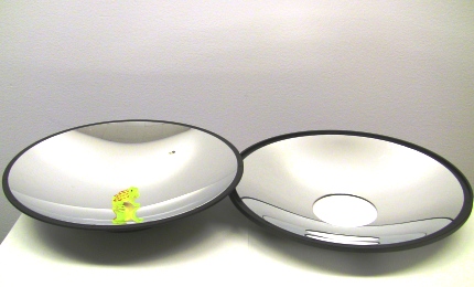
Figure 1b: A mirascope consists of two parabolic mirrors [photo taken by author].
Modeling the Mirascope Using Dynamic Technology - 2. Preliminaries and Heuristics
To begin with, we recognize the physical foundation of the mirascope. To see an image coming out of the mirascope, there has to be some light from the environment that reaches the object inside and is somehow bounced back to the outside. Therefore, we need to understand and model how light works and further explain how the human eye could recognize the position of a virtual image. For our purpose, there are two types of mirrors that are interesting: a plane mirror and a parabolic mirror.
2.1 The Plane Mirror
In the case of a plane mirror, there are two steps involved when the human eye sees a virtual image of an object in the mirror. First, there is some light that reaches the mirror and is reflected by its reflective surface to the eye, which allows the human observer to notice the image, not necessarily where it is in the mirror. Second, since there are multiple light rays that are reflected to the eye, the observer identifies the unique location of the image by the common intersection of these light rays in a process that can be called triangulation (Figures 2a, 2b). These two steps can be readily simulated using a dynamic tool like GeoGebra. Such a simulation allows us to understand how plane mirrors work, including the basic idea of geometric reflection. For simplicity, we assume, in all our examples, that the reflective surface of the mirror is coated on top of the glass, which is the case of a plastic mirascope toy. In other cases, the reflective surface is normally behind the glass and should be dealt with accordingly.
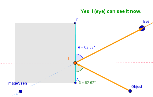
Figure 2a: How the human eye sees an object in a plane mirror.
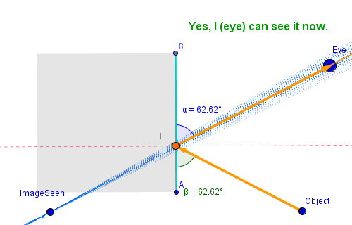
Figure 2b: How the human eye identifies the unique location of the image of an object in a plane mirror.
[Open a dynamic GeoGebra worksheet in a new window.]
2.2 The Parabolic Mirror
2.2.1 How light is reflected by a parabolic mirror
A parabolic mirror is different than a plane mirror in that it has a curved surface which reflects incoming light to different directions, depending on the curvature at a specific point of the parabola. In a mathematical sense, when a light ray reaches a particular point of a parabolic mirror, it is reflected as if the light ray was applied to a plane mirror that is tangent to the curved mirror at that point. As shown in Figure 3, when a light ray leaves the object and reaches the parabolic mirror at point \(C\), it is reflected to the eye as if it was reflected by the tangent line \(b\). If so desired, the physical terms, such as point of incidence, the normal line, the angle of incidence, and the angle of reflection, could be discussed with students. It is worth noting that because of the lack of triangulation, the human eye in Figure 3 might not be able to see a clear image of the object, which is part of the reason that the mirascope requires two parabolic mirrors. However, when the object, the eye, and the focus of a parabolic mirror are aligned in some special positions, the eye may be able to see a clear and perhaps distorted image of the object or part of the object.
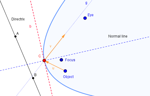
Figure 3: How the human eye might see an object in a parabolic mirror.
[Open a dynamic GeoGebra worksheet in a new window.]
2.2.2 How to find the focus of a parabola
By its very nature, a parabolic mirror has a focus, toward which all incoming light rays parallel to its principal axis or line of symmetry are reflected (Figure 4a). Therefore, to locate the focus of a parabola, we can model at least two such light rays and find the intersection of the corresponding reflected light rays. This observation is useful when a parabola is defined algebraically and thus its focus is not immediately available.
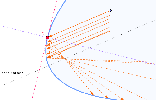
Figure 4a: How to find the focus of a parabola using incoming light rays parallel to the principal axis.
[Open a dynamic GeoGebra worksheet in a new window.]
It follows that if a parabola is defined in the form of \(f(x)=ax^2+c\), where \(a\neq 0\), its principal axis is the \(y\)-axis. We could use any two lines that are parallel to the \(y\)-axis to locate the focus of the parabola. An example is presented in Figure 4b, where the parabola is defined as \(p_u=ax^2\) with \(a>0\). We assume that two light rays parallel to the \(y\)-axis reach the upward parabola (Additional Figure 4c). Those two light rays are both reflected toward the focus, where they uniquely locate the focus of the parabola at their intersection (Figure 4b). Since the focus in our case is on the \(y\)-axis, there is, in fact, no need for a second light ray. Once the focus of the upward parabola is located, we may hide all the auxiliary objects in order to reduce the visual complexity of the construction, leaving visible only the focus \(F\) of the upward parabola (Additional Figure 4d). To hide any object in GeoGebra, we can right-click on it and toggle the "Show Object" property or toggle the radio button to the left of its definition.
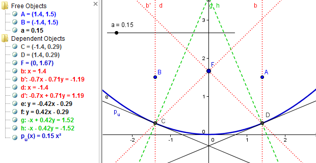
Figure 4b: Two light rays parallel to the y-axis are reflected by the parabola toward its focus.
[Open a dynamic GeoGebra worksheet in a new window.]
2.3 Design Heuristics
Having analyzed the mirrors, we now have a better grasp of the mirage effect, which simply has to do with the way light travels and the properties of mirrors. However, we still do not have a starting point to build a model for it. In search of a starting point, we focus on the object itself. For the object at the bottom of the mirascope to show up at the top, there has to be some light rays that originate from the object and are somehow reflected to the eye. Although the light comes ultimately from another source such as the surrounding lighting or a small light bulb placed inside, we could start with an arbitrary point on the object to investigate the mathematical and physical processes behind a mirascope. Our assumption is that if we could see one point of the object, we could apply the same procedure all over the object to produce the whole image.
With such a starting point in place, we still need to model the two parabolic mirrors. Given our purpose and the complexity of 3-D modeling, we choose to model the mirascope using a two-dimensional approach or rather, a cross section of the 3-D mirascope. Accordingly, we need two parabolas. While a parabola can be constructed geometrically, an exclusively geometric approach is not well suited for our modeling task since we want to align the two parabolas with high accuracy. Furthermore, in building a dynamic model, we wish to leave room for open-ended exploration, which in our case may include changing the curvature of the parabolas and/or their vertical alignment. This analysis points to an algebraic way for constructing the two parabolas. Because the specific locations of the parabolas are not essential in this case, we could use a simple algebraic form: \(f(x)=ax^2+c\), where \(a\) controls the orientation and curvature of a parabola, and \(c\) moves it vertically for alignment. To facilitate subsequent open-ended explorations, we choose to use sliders for the initial parameters, \(a\) and \(c\), of the two parabolas. These sliders are simply visual representations of the two parameters and are shown as horizontal or vertical lines on the screen. Note that the symmetric shape of the mirascope dictates that if \(a\) is positive for the parabola that opens up, \(-a\) would be used for the one that opens down.
The above analysis is an essential phase of problem solving [4]. Although it takes time and may take many iterative steps, it unveils the underlying structure of the mirascope, clarifies the interdependent relations, and ultimately helps us devise a plan of action. In my teaching experience, I found that this step could be challenging for some prospective and classroom teachers, who tend to take the problem at the surface level and thus create a mere visual replica of the given problem using a quadratic function \(f(x)=ax^2+bx+c\) without explicitly defining the mathematical relations among the integral components. Therefore, in spite of the technical utilities and representational resources of a dynamic environment such as GeoGebra, the problem solver still has to make sense of the problem before he/she could come up with a preliminary plan of action. With the analysis above, we now proceed to the construction stage, during which we may be able to learn more about the problem itself and revise our plan.
Modeling the Mirascope Using Dynamic Technology - 3. Mirascope Construction Using Geogebra
3.1 Define Two Parabolas Algebraically
In order to align the two parabolic mirrors accurately, we use algebraic functions to model the two face-to-face parabolas. We start with two constant variables, \(a\) and \(c\), where \(a\) controls the orientation and curvature of the parabolas, and \(c\) controls their vertical alignment or, in our case, the distance between the vertices of the two parabolas. For simplicity, we define \(a=0.15\) through the input box and convert it to a slider with an interval of \([0,2]\). Also, we define \(c=2\) through the input box and convert it to a slider with an interval of \([0,5]\). In GeoGebra, any free or independent variable can be converted to a slider for visualization with an initial value and an interval that defines its range of possible values. To convert an independent variable to a slider, we can right-click on the variable and enable "Show Object" or, alternatively, we could toggle the radio button to the left of a variable definition (Figure 5). A slider has other styles such as color, thickness, length, and increment, which can be changed whenever necessary. According to the above definitions, \(a\) can take any value in \([0,2]\); \(c\) any value in \([0,5]\). Both \(a\) and \(c\) could take other reasonable initial values and intervals for clear visualization. We further define \(p_u(x)=ax^2\), which will model the upward parabola, and \(p_d(x)=-ax^2+c\), which will model the downward parabola. By adjusting the values of \(a\) and \(c\), we could manipulate the shape of the mathematical mirascope. This first step to model the mirascope is illustrated in Figure 5.
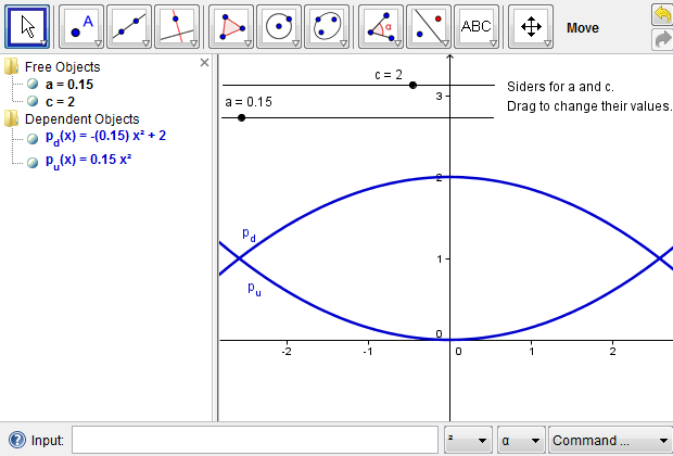
Figure 5: Construct two parabolas using an algebraic approach.
[Open a dynamic GeoGebra worksheet in a new window.]
3.2 Modeling Light Reflections Within the Mirascope
According to the previous analysis, we start with a point \(P\), which represents an arbitrary point on the object placed at the bottom of the mirascope. We further imagine a light ray that leaves point \(P\), reaches the upper parabola, is reflected to the lower parabola, and is ultimately reflected out of the mirascope through its opening. As a construction heuristic, we note that since the light ray is reflected back and forth in the mirascope, we need to choose from segments, rays, or lines as an appropriate mathematical object to model its path. Because there are cases where a line or a segment long enough may intersect a parabola at two points and thus cause construction confusion, we prefer segments or rays to lines. This is only technically necessary when GeoGebra or a similar tool is used, representing the connections and distinctions between physical ideas and mathematical ones. Whenever necessary, we could make a ray out of a segment to find the point of incidence, where the light touches the mirror. To simplify the process, we can hide the segments and other intermediate objects and then focus on the resulting ray. Additional Figures 6a and 6b show how a light ray from point \(P\) is reflected out of the mirascope.
To locate the image of point \(P\) outside the mirascope, we need at least one more light ray that originates from point \(P\) and reaches the upper mirror at a different point, for example, point \(H\). We could then repeat the whole procedure as demonstrated in Additional Figures 6a and 6b; alternatively, we could take advantage of the technological resources in the GeoGebra environment, which allows the encapsulation of a previous procedure in the form of a new tool. A tool is similar to a function that takes some inputs and produces certain outputs. For example, in finding the reflection of the first light ray, point \(P\), point \(G\), and the constants \(a\) and \(c\) are the inputs; the light ray that is reflected out of the mirascope as well as other intermediate objects could be the outputs (Figure 6c).
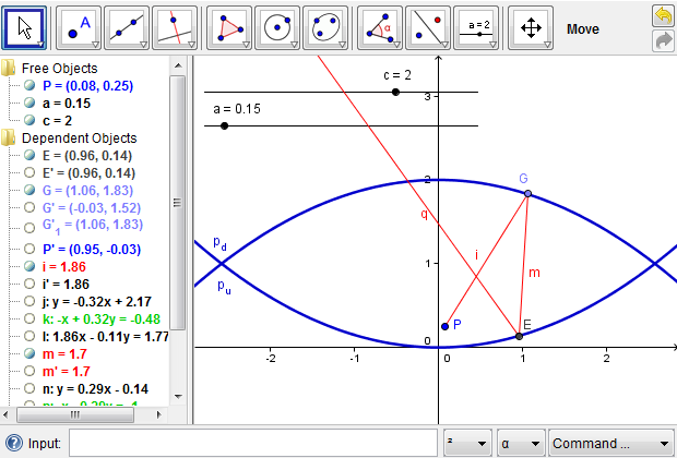
Figure 6c: A light ray from point \(P\) is reflected out of the mirascope with all intermediate steps hidden to reduce visual complexity.
[Open a dynamic GeoGebra worksheet in a new window.]
Therefore, we could define a new tool, for example, MiraReflection to simplify the whole procedure (Additional Figure 6d). Once the new tool is defined, it can be used to reflect any light ray from point \(P\) out of the mirascope without repeating the tedious procedures. Using the newly defined tool MiraReflection, we could find the reflection of the light ray that leaves point \(P\) and reaches some point \(H\) on the upper parabola (Additional Figure 6e); it meets with the first reflected light ray at point \(J\), which uniquely identifies the image of point \(P\). We now have a complete mathematical model of the mirascope, which subsequently provides more opportunities for open-ended explorations than a physical one (Figure 6f).
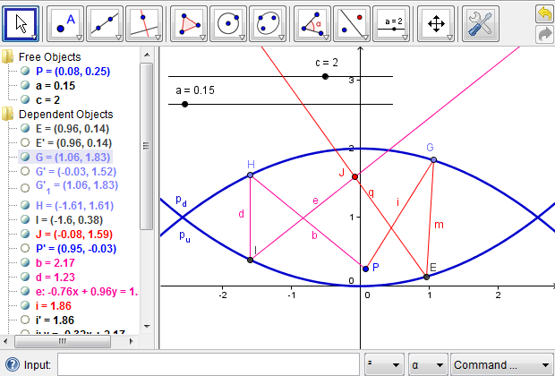
Figure 6f: Point \(J\) is the intersection of the two light rays reflected out of the mirascope and is thus the image of point \(P\).
Modeling the Mirascope Using Dynamic Technology - 4. Using the Simulation: Explorations and Exercises
Once we have constructed a mathematical mirascope, we can use it to ask in-depth questions about the mirascope and the way it works. In this section, we discuss how the simulation can be used for exercises and open-ended explorations.
4.1 Is the Whole Image Visible?
First of all, we want to see how an object placed at the bottom of the mirascope can be projected outside, using the “Trace On” feature of GeoGebra. With Trace turned on for both points \(P\) and \(J\), we can draw a small shape by dragging point \(P\), which is projected simultaneously to the top part of the mirascope (Figure 7a). Interestingly, the image is reflected about the \(y\)-axis in contrast to the orientation of the original object, which is consistent with a physical mirascope. It is noteworthy that in Figure 7a, the image is not entirely outside the mirascope, which means the observer can not see the whole image of the object. What might be the problem?
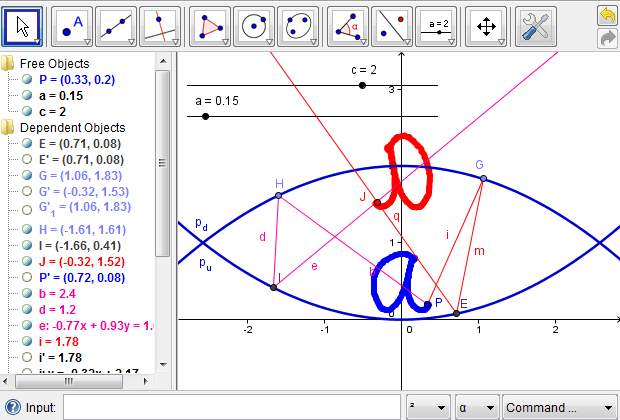
Figure 7a: A small shape is projected to the top part of the mirascope; only part of the image is actually visible.
To address the problem above, we can explore the effects of the vertical distance between the two parabolas on the position of the image. For example, what would happen if the two parabolas are farther apart? Since we used a slider for the parameter \(c\), we can now drag the point on it to change the \(c\) value to any reasonable number and simulate the mirage effect (Figure 7b). Similarly, what would happen to the image if the two parabolas are very close or, in other words, \(c\) has a small positive value? What might be an ideal case where the whole image is projected outside the mirascope? We leave these questions as exercises for the readers.
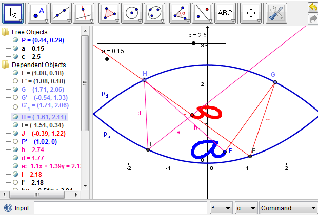
Figure 7b: When the two parabolas are far apart, a small shape is projected within the mirascope, invisible to the observer.
[Open a dynamic GeoGebra worksheet in a new window.]
4.2 Are More Light Rays Necessary to Locate the Image of a Point?
Second, we want to see if there is need for more light rays in order to uniquely locate the image of point \(P\). In the previous steps, we assumed that there is a certain light ray that leaves point \(P\) and reaches the upper parabola at a certain point, for example, point \(G\) or \(H\). We did not impose any constraint on the position of point \(G\) or \(H\). Therefore, points \(G\) and \(H\) could be anywhere on the upper parabola. To see if we need more light rays, we can turn on the Trace feature for the light ray that leaves the mirascope and allow point \(G\) or \(H\) to move along the upper parabola. As shown in Additional Figure 7c, all the resulting light rays intersect at the same point, which implies that we only need to model two light rays in order to locate the image of point \(P\), which is point \(J\) in the Figure 6f.
4.3 Exercises
We now pose a few questions to entertain the readers' curiosity, inviting them to experiment with the simulation and ask other interesting questions of their own choice. Either one of the previous web pages can be used as a starting point with a varied degree of support and complexity. To facilitate the exploration, we provide a full-sized mirascope, which can be re-exported as a web page or saved as a GeoGebra file by following options in the File Menu.
Exercise 1. The simulation allows us to answer questions about special cases. Using the mirascope provided above, please find out what would happen if the two parabolas are close to each other? (see Additional Figure 7d).
Exercise 2. In a real mirascope, the two parabolas are aligned in such a way that the vertex of one is at the focus of the other. In section 2.2, we discussed a method to find the focus of a parabola. Using that method, find the focus of the upward parabola. Then, change the value of \(c\) so that the vertex of the downward parabola is at the focus of the upward one. Simulate the mirage effect and describe what you see (dynamic web page).
Exercise 3. Distortion occurs when the object is projected by the mirascope. Change the relative distance between the two parabolas and see how it affects the amount of distortion.
Exercise 4. For an observer to see the image projected on top of the mirascope, there needs to be an opening in the top parabola. Given the size of a small object, how can we find the right size for the opening? Hint: the opening should be large enough for each point of the object to be projected outside. By tracing both of the outgoing light rays, we can determine the size of the opening (see Additional Figure 7e).
Exercise 5. As mentioned in section 2.2.1 about a parabolic mirror, when the eye, the object, and the focus are aligned in certain ways, the observer may be able to see a clear image of the object. Using methods discussed above, find what the observer may be able to see in such special cases (see Additional Figure 9 or a dynamic web page).
4.4 Managing Complexity
Finally, we reiterate the importance of complexity management during a design process. Since there are several layers of algebraic and geometric operations involved, we may get overwhelmed, at least visually, by the intermediate objects created in modeling the mirascope. Therefore, we should conduct some maintenance work at each step, both cognitively and logistically, before proceeding to the next one. GeoGebra provides a convevnient feature for hiding any object. To do so, we could right click on an object and toggle "Show Object," or, alternatively, we could toggle the radio button to the left of each object definition. Furthermore, we could define a new tool to simplify a procedure that is useful in subsequent phases of design. A full picture of the mirascope project is illustrated in Figure 8, which highlights the need to manage complexity in a complex design project.
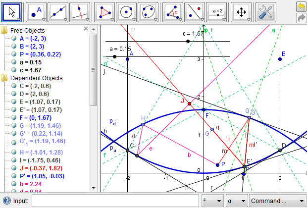
Figure 8: The full picture of the mirascope project, which shows the significance of managing complexity in the design processes.
Modeling the Mirascope Using Dynamic Technology - 5. Conclusion
The mirascope provides a worthwhile task to engage prospective and inservice mathematics teachers in the exploration of an appealing physical phenomenon and the development of genuine problem solving skills in STEM-oriented classes. In the beginning, little was clear about the mathematical mechanism underlying the mirage effect of a popular toy. We did not even know how to get started or how to manage the complexity. Through problem analysis, we came to understand the essence of the problem, which involves the properties of light and those of a parabola. The mirage is simply the optical projection of a small object placed at the bottom. To model the parabolic mirrors, we chose to use algebraic forms for accuracy and ease of control. To simulate the light reflection processes, we chose to start with an arbitrary point on the object and use geometric reflections to establish the paths of light. In enacting the reflection procedures, we were guided by our overarching conceptual understanding of the mirascope, thus integrating both conceptual and procedural aspects of the dynamic construction. The resulting mathematical mirascope does not only illustrate how the mirascope works, but also allows us to address other hypothetical what-if and what-if-not questions [1] about the physical mirascope. The mirascope project, with its various levels of scaffolding and starting points, could be implemented by readers who are interested in bringing meaningful STEM content into teacher education and middle and secondary mathematics classrooms and those we seek to teach big ideas of mathematics using new technologies. Similar projects can be found in professional journals [5] that showcase the integration of algebra and geometry in real-world and physical situations. Those interested in obtaining a physical mirascope can search for mirascope at an online store such as amazon.com or visit OPTI_GONE International, one of the original makers of the Mirage®. For further information about the physics of light and optical microscopy, please refer to the Optical Microscopy Primer.
Acknowledgements
The author would like to thank the two anonymous reviewers and the journal editors for their encouragments and constructive recommendations regarding an earlier version of the article. Yazan Alghazo and Michaell Bu reviewed drafts of the dynamic designs and asked thoughtful questions about the mirascope and related mathematical ideas, which are incoporated into the present article.
References
- Brown, S. I., & Walter, M. I. (2005). The art of problem posing (3rd ed.). Mahwah, NJ: Lawrence Erlbaum Associates.
- Hohenwarter, M., & Preiner, J. (2007). Dynamic mathematics with GeoGebra. Journal of Online Mathematics and Its Applications, 7. Retrieved May 1, 2010 from this site
- Jacobs, H. R. (1982). A teachers' guide to mathematics: a human endeavor (2nd ed.). San Francisco: W. H. Freeman.
- Polya, G. (1973). How to solve it: A new aspect of mathematical method (2nd ed.). Princeton, NJ: Princeton University Press.
- Siegel, L. M., Dickinson, G., Hooper, E. J., & Daniels, M. (2008). Teaching algebra and geometry concepts by modeling telescope optics. Mathematics Teacher, 101(7), 490-497.
About the Author
Lingguo Bu is an assistant professor of Mathematics Education in the Department of Curriculum and Instruction at Southern Illinois University Carbondale. He is interested in the use of interactive and dynamic learning technologies in support of mathematical modeling in school mathematics and in preservice and inservice mathematics teacher development.
Modeling the Mirascope Using Dynamic Technology - Additional Figures
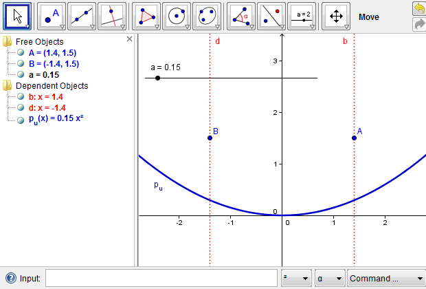
Figure 4c: Two light rays that are parallel to the \(y\)-axis reach an upward parabola.
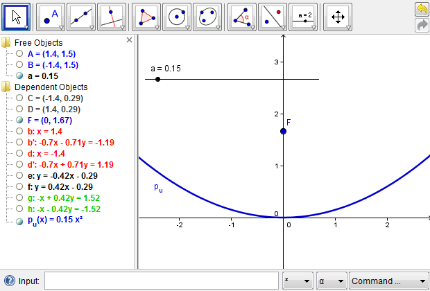
Figure 4d: Hide the intermediate steps to reduce the construction complexity.
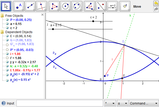
Figure 6a: A light ray from point \(P\) reaches the upper parabola and is reflected to the lower one.
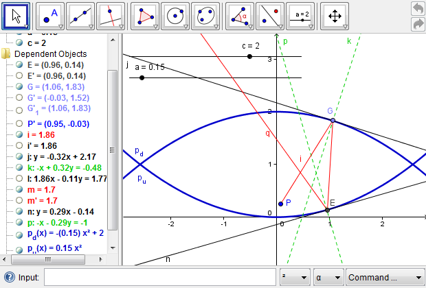
Figure 6b: A light ray from point \(P\) is reflected out of the mirascope.
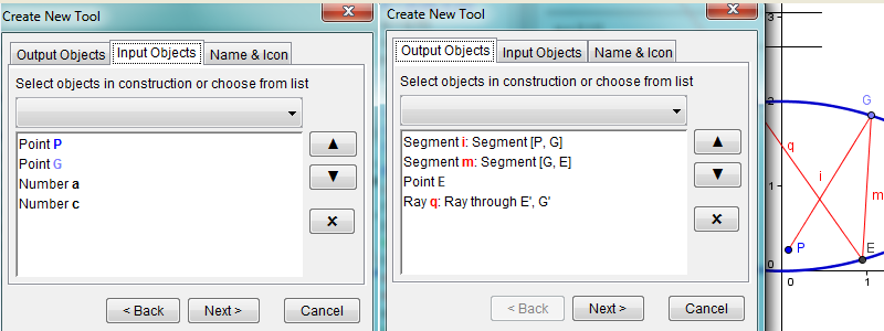
Figure 6d: Defining a new tool to reflect light from point \(P\) out of the mirascope. In GeoGebra, click "Tools" in the menu, select "Create New Tool," and follow the onscreen directions to click the objects involved. In our case, inputs include point \(P\), point \(G\), number \(a\), and number \(c\). Outputs may include all the objects related to the light reflection or, if so desired, the light ray \(q\) only.
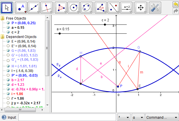
Figure 6e: Using the newly defined tool to reflect a second light ray from point \(P\) out of the mirascope. In GeoGebra, place point \(H\) anywhere on the downward parabola. Point \(H\) is the location where a second ray from point \(P\) touches on that parabola. Next, click the button for the new tool at the upper-right corner. For inputs, click point \(P\) and point \(H\). When prompted for numbers, type "a" and "c". The color of the second ray is changed to distinguish it from the first one.
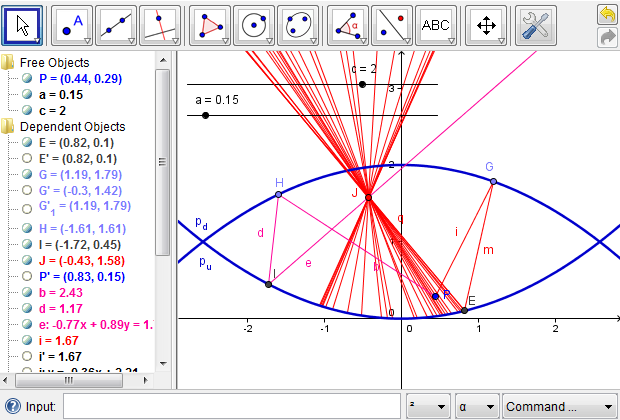
Figure 7c: Modeling more light rays from point \(P\) is not necessary to locate the image of \(P\).
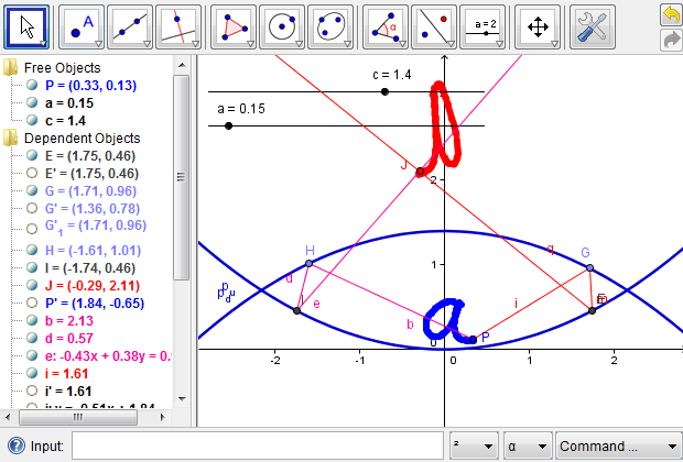
Figure 7d: The image is well above the mirascope if the two parabolas are relatively close to each other.
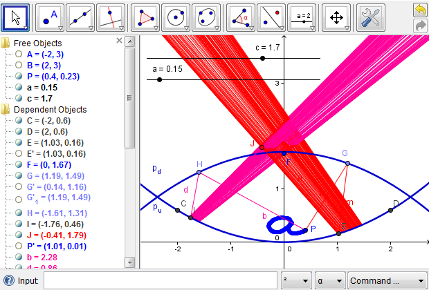
Figure 7e: Finding the appropriate opening by tracing the outgoing light rays.
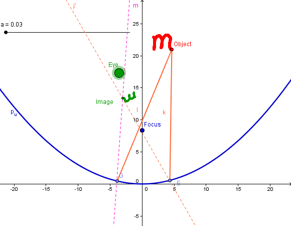
Figure 9: When the eye, the object, and the focus of a parabolic mirror are aligned in certain ways, one may be able to see a clear image with changes in its size and orientation.