- About MAA
- Membership
- MAA Publications
- Periodicals
- Blogs
- MAA Book Series
- MAA Press (an imprint of the AMS)
- MAA Notes
- MAA Reviews
- Mathematical Communication
- Information for Libraries
- Author Resources
- Advertise with MAA
- Meetings
- Competitions
- Programs
- Communities
- MAA Sections
- SIGMAA
- MAA Connect
- Students
- MAA Awards
- Awards Booklets
- Writing Awards
- Teaching Awards
- Service Awards
- Research Awards
- Lecture Awards
- Putnam Competition Individual and Team Winners
- D. E. Shaw Group AMC 8 Awards & Certificates
- Maryam Mirzakhani AMC 10 A Awards & Certificates
- Two Sigma AMC 10 B Awards & Certificates
- Jane Street AMC 12 A Awards & Certificates
- Akamai AMC 12 B Awards & Certificates
- High School Teachers
- News
You are here
Creating Photo-realistic Images and Animations
4. Creating the Dodecahedron
We will create an image of a dodecahedron in four steps, introducing new elements as required. Our first image will simply show the background color. Then we will create images of one cylinder, five cylinders in the shape of a pentagon, and finally the fully assembled dodecahedron. To clarify the exposition, the new or modified code at each step will appear in bold type.
Background Color:
Cut and paste the following two lines into your editor. Save the file as dodec-01.pov.
The first line is a comment containing the shell command for rendering the image. Here is what it means:
-
“
-
-
-
-
The second line indicates that the background of the scene will be dark blue. This is given by a red-green-blue 3-vector whose components can run from 0 to 1.
If you are using Windows or Mac GUI interface, you can simply click the “Run” button. If you are using Linux, you can cut and paste the first line (excluding the double slash which indicates a comment) into your shell. This first line is not required, but I find it a convenient way to reproduce the exact scene when running the code at a later time.
What you should see is a 640x360 dark blue scene.
Single Cylinder:
Our dodecahedron will be constructed using 30 cylinders, so let's start by creating an image with a single cylinder. Cut and paste the following code into your editor and save the file as dodec-02.pov. (Changes from dodec-01.pov above are indicated in boldface.)
The rendered image should look like Figure 2:
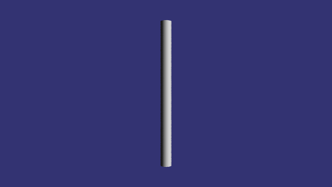
Figure 2: A cylinder
In order to see the object, we need a camera and the object must be illuminated.
To describe the camera, we give it's location in 3-space, the direction of its “up” and “right” vectors, the direction it is looking and the viewing angle. A large viewing angle corresponds to a wide angle lens, allowing more of the scene to be rendered. The right vector might at first seem strange since it points in the negative x direction. I've done that because POV-Ray uses a left handed coordinate system by default. Specifying the right vector in this way transforms the coordinate system into the familiar right handed system that mathematicians and physicists love so well (positive z axis up, positive x axis to the right and positive y axis into the screen). The factor of 1.78 gives the relative width to height of the image: in this case, common 16:9 format seen in high definition video. Similarly, to define the light source we give its location in 3-space and its color vector (using red-green-blue components).
To verify that the coordinate system behaves as expected, let's add a translate directive to the description of the cylinder:
This translates the cylinder to the right along the x axis. Repeating by translating along the positive y and z axes give the expected results (Figure 3):


Figure 3: Translation
Adding Texture:
You can define the light scattering properties of a surface by using primitives that give specular reflectivity, diffuse reflectivity, transparency and so on. Or you can use one of the hundreds of predefined textures. To do that, a texture definition file must be included with your scene file. Save the following code as dodec-03.pov and render it (Figure 4). (Changes from dodec-02.pov above are indicated in boldface.)
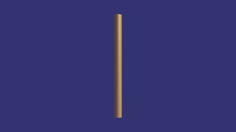
Figure 4: Changing the texture
Michael Grady (Southern Utah Univ.), "Creating Photo-realistic Images and Animations," Convergence (September 2010), DOI:10.4169/loci003351