A Gallery of Ray Tracing for Geometers
Abstract:
Modern expositors of mathematics, with computers and open source ray tracing software at their disposal, have the tools necessary to create vivid and effective geometric constructions in 3-space. With a little additional effort, animations can be generated, adding the fourth dimension of time. The web provides a viable medium for enhancing mathematical presentations with photo-realistic graphics and video.
Contents:
Some of the images in this article have associated animations, indicated in the figure caption by the phrase “with linked animation.” Click on the image to view the animation in a new browser window or tab -- these animations are in 1280x720 Quicktime format, so your browser or operating system must be configured (with the Apple Quicktime Player or compatible software) to launch them properly. The animation files are large, so they may take a few minutes to load in your browser.
A Gallery of Ray Tracing for Geometers
1. Introduction
Modern expositors of mathematics, with computers and open source ray tracing software at their disposal, have the tools necessary to create vivid and effective geometric constructions in 3-space. With a little additional effort, animations can be generated, adding the fourth dimension of time. Expository material of this kind is often excluded in ordinary print publication due to the high cost. In contrast, the web provides a viable medium for enhancing mathematical presentations with photo-realistic graphics and video.
The recent videos Mobius Transformations Revealed [1] and Dimensions [2] are two examples of the use of the open source ray tracer POV-Ray to create wonderfully effective animations for showcasing beautiful mathematical ideas.
The POV-Ray scene description language is well suited for geometric construction. It is our experience that the task of creating effective images and animations is a mathematical activity requiring mathematical thinking, in much the same way as with the classical Euclidean constructions using straightedge and compass.
The purpose of this article is to introduce ray tracing as a tool for mathematical exposition. It will not escape the interested reader that it can also serve as a powerful tool for mathematical exploration and experimentation.
We begin with a gallery of mathematical images to illustrate what can be done using ray tracing. Ten images are shown illustrating various geometric concepts. Six of these images have associated animations, indicated in the figure caption by the phrase “with linked animation.” Click on the image to view the animation (these are in 1280x720 Quicktime format, so your browser or operating system must be configured to launch them properly).
2. Photorealism
Ray tracers are great tools for creating vivid, photo-realistic images. Properly utilized, they can enrich the mathematical exposition. For example, suppose we wish to define and illustrate the concept of polyhedral duality as it applies to the regular solids. Let's first construct the sphere which circumscribes an icosahedron (Figure 1). The icosahedron intersects the sphere at its 12 vertices.
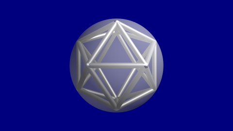
Figure 1: Icosahedron circumscribed by a sphere.
Planes tangent to the sphere at each of the 12 vertices will bound another polyhedron: the dodecahedron, shown in Figure 2. Polyhedra related in this way are said to be “duals”. Note that the sphere which circumscribes the icosahedron is also inscribed in the dodecahedron, which it touches at the centers of each face. Equivalently, the vertices of the icosahedron mark the centers of the faces of its dual.
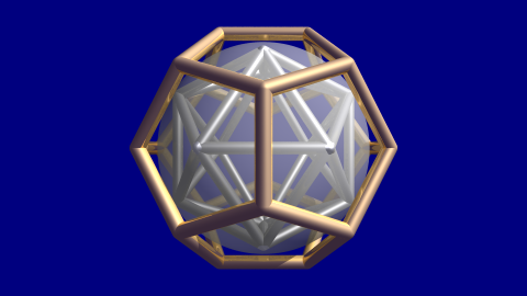
Figure 2: The dodecahedron with faces tangent to sphere.
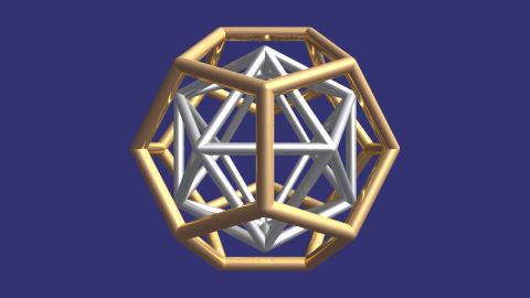
Clearly, this construction can be continued indefinitely at both larger and smaller scales. Just as clearly, both polyhedra have the same symmetry group [3], the Icosahedral group. The full group (including reflections) has order 120 and the rotation subgroup has order 60 [4]. Figure 3 has a linked animation showing the two polyhedra rotating a full turn.
A Gallery of Ray Tracing for Geometers
3. Projections
Projections are of fundamental importance in geometry, and ray tracers make them easily visible. Riemann, for example, used stereographic projection in his model of the complex plane. The POV-Ray generated video Mobius Transformations Revealed provides a beautiful exposition of Riemann's brilliant insight into the geometry of the Mobius functions where translations, dilations, rotations and inversions are all revealed to correspond to simple motions of the sphere [1].
Figure 4 depicts a sphere tangent to a plane at its south pole. There are three circles: the equator in yellow (a great circle) and two general circles passing through the north pole (in black). A point light located at the north pole projects the equator onto a circle concentric with the south pole. Circles passing through the poles are projected onto lines [5].
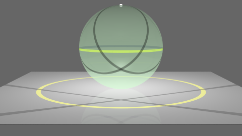
Figure 4: Stereographic projection of circles onto the plane.
Figure 5 is a view of the same scene looking down on the plane from above.
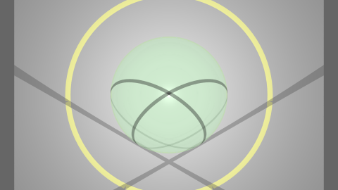
Figure 5: Top view of the scene in figure 4.
Figure 6 depicts the central projection of a dodecahedron onto the sphere. This gives a regular partition of the sphere into 12 congruent spherical pentagons. The same process can be repeated for the other regular solids. Felix Klein used central projection in his study of the finite groups of rotations in three dimensions [6, p.3-30]. Using a ray tracer, projections like this come for free: just place a light at the center of the sphere and let the shadows of the edges of polyhedron fall on the surface of the sphere. Rotating the dodecahedron, as shown in the accompanying animation, reveals this projection more vividly.

Figure 6 with linked animation: Central projection.
A Gallery of Ray Tracing for Geometers
4. Reflections
Ray tracers are unequaled in their ability to simulate reflection. For geometers, this makes it possible to model and investigate reflection groups. A single reflection corresponds to a single mirror. If an object is placed in front of this mirror, the object and its reflection can be seen. We say that a single reflection generates a group of order 2 [7, p.75]. When the object is placed between two parallel mirrors, there can be an unlimited number of reflections. In other words, two parallel reflections generate an infinite group. This configuration is modeled in Figure 7, which shows several of the images of a cylinder and a triangle in two parallel mirrors. Ray tracers allow one to set the maximum number of reflections that will be computed before fixing the color of a pixel in order to limit the time required to render an image. In this case, we have set the “maximum trace level” to 16. Close inspection of the linked animation will reveal that the group generated is the infinite dihedral group [7, p.75].
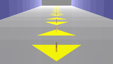
Figure 7 with linked animation: Reflection in two parallel mirrors.
Figure 8 models what happens when two mirrors are set at a dihedral angle of \(\pi/4\) and a sphere is placed between them. As we can see, eight images are generated, and in fact the two reflections generate the dihedral group \(D_4\). The animation shows what happens when the sphere is moved closer and closer to the line of intersection of the two mirrors. Setting the angle between the mirrors to be any submultiple of \(\pi\) will generate a corresponding dihedral group [7, p.77].
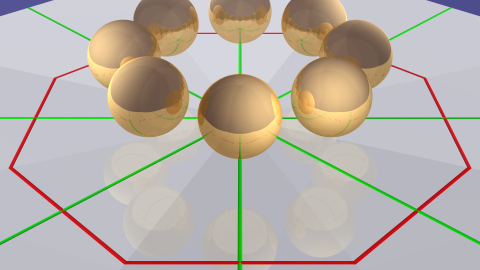
Figure 8 with linked animation: Reflection in two mirrors at dihedral angle π/4
Three mirrors arranged in the proper configuration will generate a finite group [7, p.81]. Figure 9 illustrates what happens when the dihedral angle between the three pairs of mirrors is \(\pi/2\), \(\pi/3\) and \(\pi/5\). What is going on is quite remarkable. This truncated dodecahedron is actually the image of a single cylinder reflected numerous times in the three mirrors. The accompanying animation illustrates what is seen when this single cylinder moves towards the viewer.
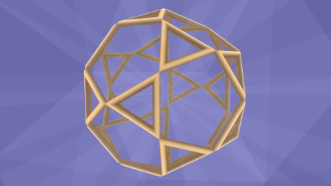
Figure 9 with linked animation: Reflection of single cylinder in three concurrent mirrors
A Gallery of Ray Tracing for Geometers
5. Rotations
Other isometries of Euclidean space, such as rotation, can be effectively illustrated using animation. Consider Klein's statement “The rotations which bring one of the regular solids into coincidence with itself collectively form a group” [6, p.5]. Using a ray tracer, you can illuminate this idea in a manner not possible in the real world. You can model two copies of the solid: one stationary and the other in rotation. Figure 10 and its corresponding animation show how this approach can be used to demonstrate the five-fold rotational symmetry of the dodecahedron. As with several of the examples given above, the animation illustrates the mathematical concept with a vividness difficult to achieve in any other way.

Figure 10 with linked animation: Five-fold rotational symmetry of the dodecahedron
Want to learn more? The companion paper “Creating Photo-realistic Images and Animations using POV-Ray” explains the third image in detail, providing an introduction to both image and animation generation and allowing interested readers the opportunity to launch their own investigations.
6. References:
[1] Arnold, Douglas, and Jonathan Rogness, Mobius Transformations Revealed (video) http://ima.umn.edu/~arnold/moebius.
[2] Leys, Jos, Etienne Ghys, and Aurélien Alvarez, Dimensions (video) www.dimensions-math.org.
[3] Hilbert, David, and Stephen Cohn-Vossen, Geometry and the Imagination (reprinted 1999: AMS), p. 90.
[4] Burn, R.P., Groups: A Path to Geometry (1985: Cambridge Univ. Press), p.57-59.
[5] Needham, Tristan, Visual Complex Analysis (1997: Oxford Univ. Press), p.140-142 http://www.usfca.edu/vca/.
[6] Klein, Felix, Lectures on the Icosahedron (reprinted 2003: Dover).
[7] Coxeter, H.S.M., Regular Polytopes (reprinted 1973: Dover).