Bridging the Gap Between Theory and Practice: Astronomical Instruments - Design and Construction of Astronomical Instruments
Design and Construction of Astronomical Instruments
I will not go into the the technical details of the astronomical instruments that were designed and constructed the two times that Ancient Mathematical Astronomy ran at SUNY Oneonta. For each instrument described below, there are one or more links to Internet pages with more information, including images of historical specimens. There are furthermore plenty of good sources on the topic of astronomical instruments, including James Evans' book listed above, which has an extensive bibliography. Thus, the following is a general presentation of the instruments that were designed and constructed in Fall 2010 and Fall 2014.
Instrument design phase
For the design phase of the course, the students in the class were divided into several groups. In Fall 2010, there were six groups with two students each and one group with three students (the third being the auditor), and in Fall 2014 there were three groups with three students each and one group with two students. Each group decided on an instrument to design. The choice of instrument was made in consultation with me and with feedback from Anderson, who provided information on whether the group's first ideas for designing the instrument were feasible with the equipment available.
The following table shows the choices of instruments and how many groups undertook to design each of them in Fall 2010 and Fall 2014.
| Instrument | Fall 2010 | Fall 2014 | |
| Armillary sphere | 2 | 1 | |
| Astrolabe | 1 | 0 | |
| Jacob's staff | 1 | 0 | |
| Quadrant | 0 | 1 | |
| Sextant | 1 | 1 | |
| Sundial | 2 | 0 | |
| Telescope | 0 | 1 | |
| Total | 7 | 4 |
After the formation of the groups and final decisions on the instruments, each group began to research their instrument. This research culminated in an instrument paper, as described above, after which the group began the actual design process.
Eight class periods of the course were used exclusively for the students to work on their designs. Anderson and I were both available at those times (or an appointment could be made to meet with one or both of us at another time). When meeting with Anderson or me, the students would explain what parts would be involved, provide sketches and dimensions, and justify that the parts would fit together so as to make the instrument functional. Some of the instruments required only a few parts, others more. Anderson and I would discuss the students' ideas and designs, address mistakes, and make suggestions. Students were expected to follow a timeframe that allowed for Anderson to construct a specimen for each group by the last week of the semester for presentation to the other students in the course.
Machines and materials used
As has already been mentioned, SUNY Oneonta owns a 3D printer, which serves the School of Natural and Mathematical Sciences (in Fall 2010, before the restructuring of SUNY Oneonta from two large academic divisions to five schools, it served the Division of Science and Social Science) and is operated by the college's Science Technician, Allen Anderson. This was the machine used for most of the parts of the astronomical instruments designed by the students in Fall 2010. However, in contrast to Fall 2010, the 3D printer was not used at all to produce parts for the instruments designed in Fall 2014. This was partly due to the 3D printer not being operational at the beginning of the semester, prompting the students and Anderson to consider alternatives.
The SUNY Oneonta 3D printer operated by Anderson is a Dimension BST-768. The machine prints in a very strong ABS plastic and has an \(8''\times 8''\times 12''\) build volume. The models created by the machine are functional and even machinable. The machine requires an STL file to generate a model. At SUNY Oneonta, Anderson uses SolidWorks to generate the required STL file, though there are also scanning devices that can be used to generate the file directly. At this point in time, the Dimension BST-768 is an old machine in terms of material and technology. It was one of the first commercially available 3D printers, and there have been many improvements made since then. The biggest issue with SUNY Oneonta's 3D printer is the resolution of detail, which is limited by the size of the material “stream” that is used to create whatever model is being printed. The resolution of the Dimension BST-768 is on the order of \(0.003''.\)
In addition to the 3D printer operated by Anderson, the Department of Art at SUNY Oneonta owns a 3D printer as well. The Department of Art's 3D printer is also a Dimension and similar to the one operated by Anderson, though it is a newer model. Recently, in Fall 2014, the Department of Mathematics, Computer Science, and Statistics also acquired a 3D printer. This 3D printer, a MakerGear M2, is a low-end desktop 3D printer. However, the 3D printers of the Department of Art and the Department of Mathematics, Computer Science, and Statistics have not been used for the construction of instruments in Ancient Mathematical Astronomy.
Besides the 3D printer, other tools were used as well to construct parts out of metal, wood, and plastic. For example, the construction of the wooden quadrant in Fall 2014 was done with a handheld electric saw.
Notes on the design and construction phases
Overall, no insurmountable obstacles were encountered while designing and constructing instruments. Certain things took longer than anticipated and others were more difficult for the students than expected. In particular, given difficulties and time constraints, we had to change plans for a few instruments, namely, the astrolabe and the telescope. Still, overall we were on track with the timeframe that I had in mind, and in both Fall 2010 and Fall 2014 the students were able to present their instruments to the class at the end of the semester.
Due to a combination of time constraints and cloudy weather at the end of the course in both Fall 2010 and Fall 2014, we unfortunately did not end up doing much in terms of using the instruments practically. Had the time been available, I would have liked to, for example, mark the shadow of the sundials at regular time intervals during the day and to measure the angular distance between two heavenly bodies with the Jacob's staff and the sextant at night. However, it turned out to be too difficult to organize it during the end-of-semester rush.
Bridging the Gap Between Theory and Practice: Astronomical Instruments - Three Armillary Spheres
Three Armillary Spheres
An armillary sphere is essentially a model of the sky, which is constructed by a number of rings on the same sphere. The system has the earth as its center, and the rings represent astronomically important features such as the celestial equator, the ecliptic, and the tropics. The armillary sphere is an ancient astronomical instrument that was used in both ancient Greece and ancient China, and by later cultures.
For more information about the armillary sphere, the Starry Messenger Project, developed by the Whipple Museum of the History of Science and the Department of History and Philosophy of Science at Cambridge University, has a website dedicated to the instrument at http://www.hps.cam.ac.uk/starry/armillary.html. In addition, Convergence has an image of a beautiful Italian armillary sphere from 1550 CE at http://www.maa.org/publications/periodicals/convergence/mathematical-treasures-italian-armillary-sphere.
A total of three groups undertook to design an armillary sphere, two in Fall 2010 and one in Fall 2014.
One of the groups that undertook to design an armillary sphere in Fall 2010 produced the most successful instrument of that course. Both members of the group worked hard and were enthusiastic throughout. Their armillary sphere was simplified in that it did not possess all of the items usually found on such an instrument (such as the arctic circles), but it had the main features, including the equator, the tropics, and the ecliptic.
The parts of the armillary sphere were movable, though not sufficiently so to be used for serious purposes. As such, the armillary sphere served more of an instructional purpose. The instrument was constructed mainly of parts created by the 3D printer. All of the rings and legs were printed on the 3D printer. The heavenly sphere of the instrument was attached to the main body of the instrument by iron pins to allow for the main body to rotate.
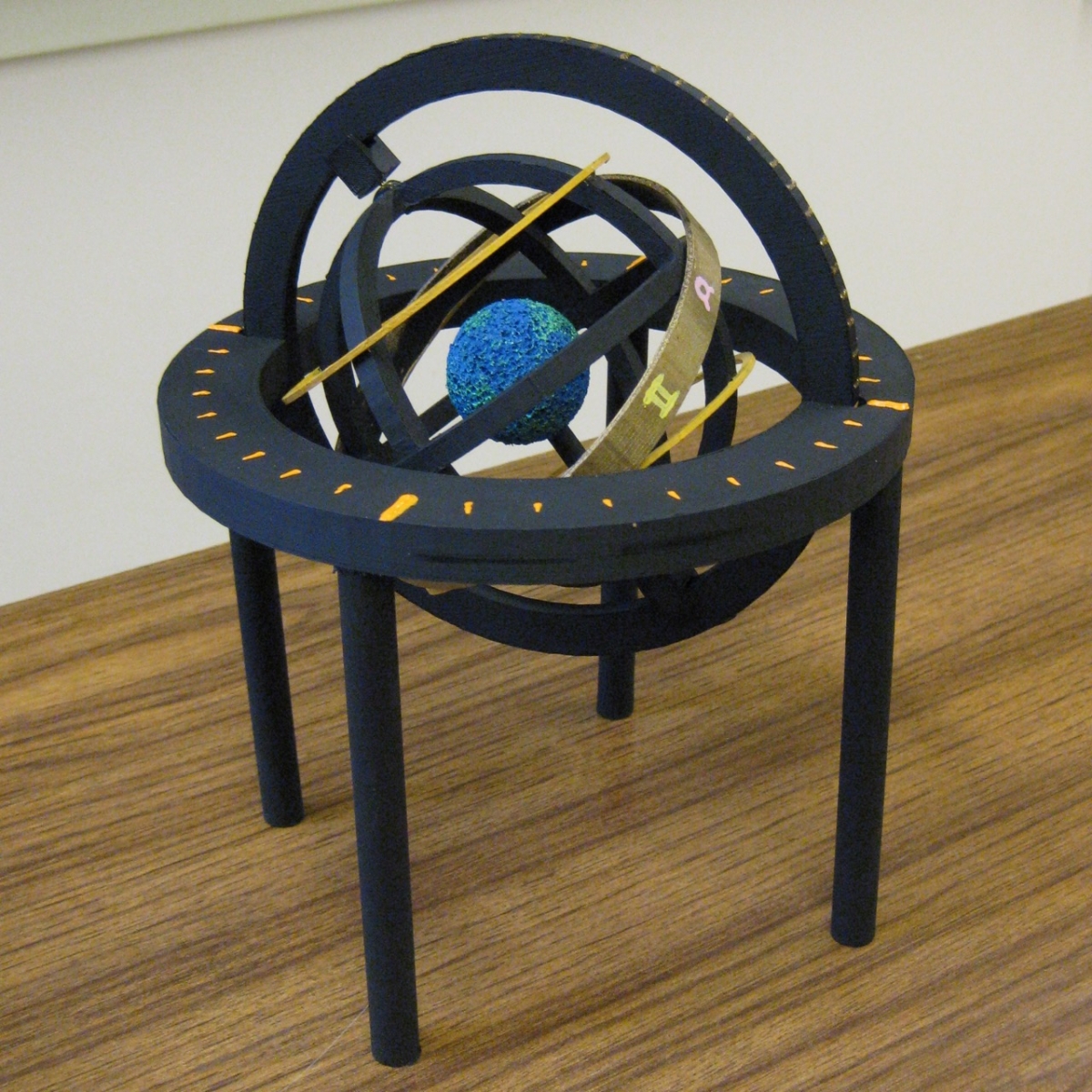
Figure 1. Student-built armillary sphere from Fall 2010 Ancient Mathematical Astronomy class (photograph by Toke Knudsen)
The armillary sphere is shown in the photo above. It is visually pleasing and could easily serve in an instructional capacity.
Another group undertook to design an armillary sphere in Fall 2010. In this case, the rings were made by the 3D printer and an iron stick was used as the central axis.
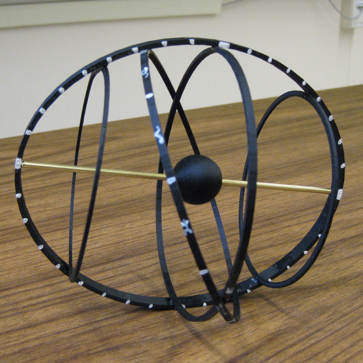
Figure 2. Another student-built armillary sphere from Fall 2010 Ancient Mathematical Astronomy class (photograph by Toke Knudsen)
The second armillary sphere from the Fall 2010 class is shown in the above photo. As can be clearly seen, the instrument did not ultimately fit together as was intended, and it was never attached to a body that would allow for it to be displayed properly or used.
In Fall 2014, one group decided to design an armillary sphere. Based on my experience from Fall 2010, I had no objections to this choice.
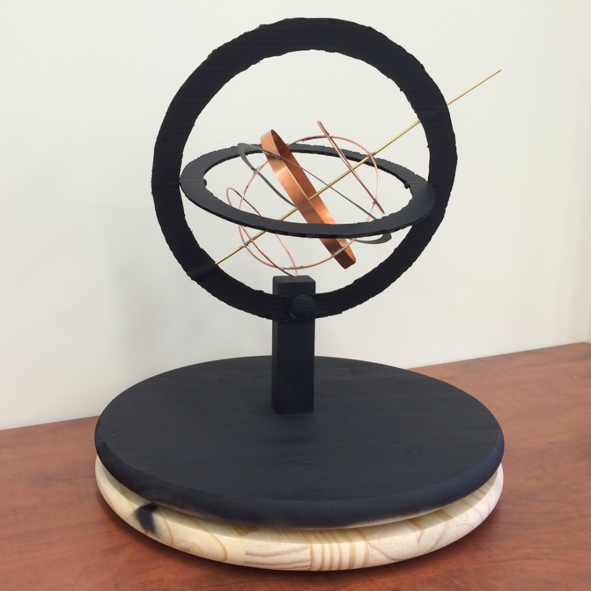
Figure 3. Student-built armillary sphere from Fall 2014 Ancient Mathematical Astronomy class (photograph by Toke Knudsen)
The above photo shows the armillary sphere from Fall 2014. The parts for this armillary sphere were made without using the 3D printer. The base consists of two circular wooden pieces, allowing for the instrument to rotate. The rings representing the celestial sphere are made from plastic, while the body of the instrument is made of copper rings constructed by Anderson. The instrument has the equator, the tropics, and the ecliptic, as was the case with the armillary spheres from Fall 2010.
While visually pleasing and able to serve as an instructional tool, the instrument was less successful than the best one from Fall 2010. For example, the main body of the instrument is too heavy for the plastic rings, for which reason the instrument droops slightly. The angles between the equator and the tropics are also not correct. These are somewhat minor things, however, that could have been corrected had there been more time available.
Bridging the Gap Between Theory and Practice: Astronomical Instruments - A Quadrant
A Quadrant
A quadrant is an instrument used to measure the angle between a heavenly body and the horizon; that is, the altitude of a heavenly body. The instrument is a quarter of a circle with the circumference portion divided into 90 degrees.
For more information about the quadrant, Epact, an electronic catalogue of medieval and renaissance scientific instruments from four European museums, has an article dedicated to the quadrant at http://www.mhs.ox.ac.uk/epact/article.php?ArticleID=14. In addition, the Starry Messenger Project, developed by the Whipple Museum of the History of Science and the Department of History and Philosophy of Science at Cambridge University, has a website dedicated to the quadrant and the sextant at http://www.hps.cam.ac.uk/starry/quadrant.html.
One group in Fall 2014 decided to construct a quadrant. The group's quadrant was made of wood, and, with a radius of \(47.75'',\) it is a large instrument. The group made the decision to make a large instrument because its accuracy would be significantly greater than that of a small, handheld quadrant. In other words, the larger the quadrant, the more accurately one can determine the altitude of the celestial body in question.
The quadrant was designed and constructed entirely by the students, who used the workshop belonging to one of them for the construction part.
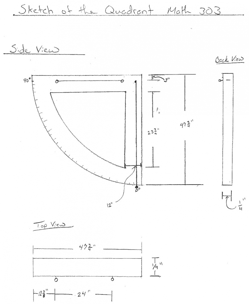
Figure 4. Student plans for a quadrant from Fall 2014 Ancient Mathematical Astronomy class
Figure 4 shows the group's sketch of a quadrant. The design of the instrument followed this original sketch.
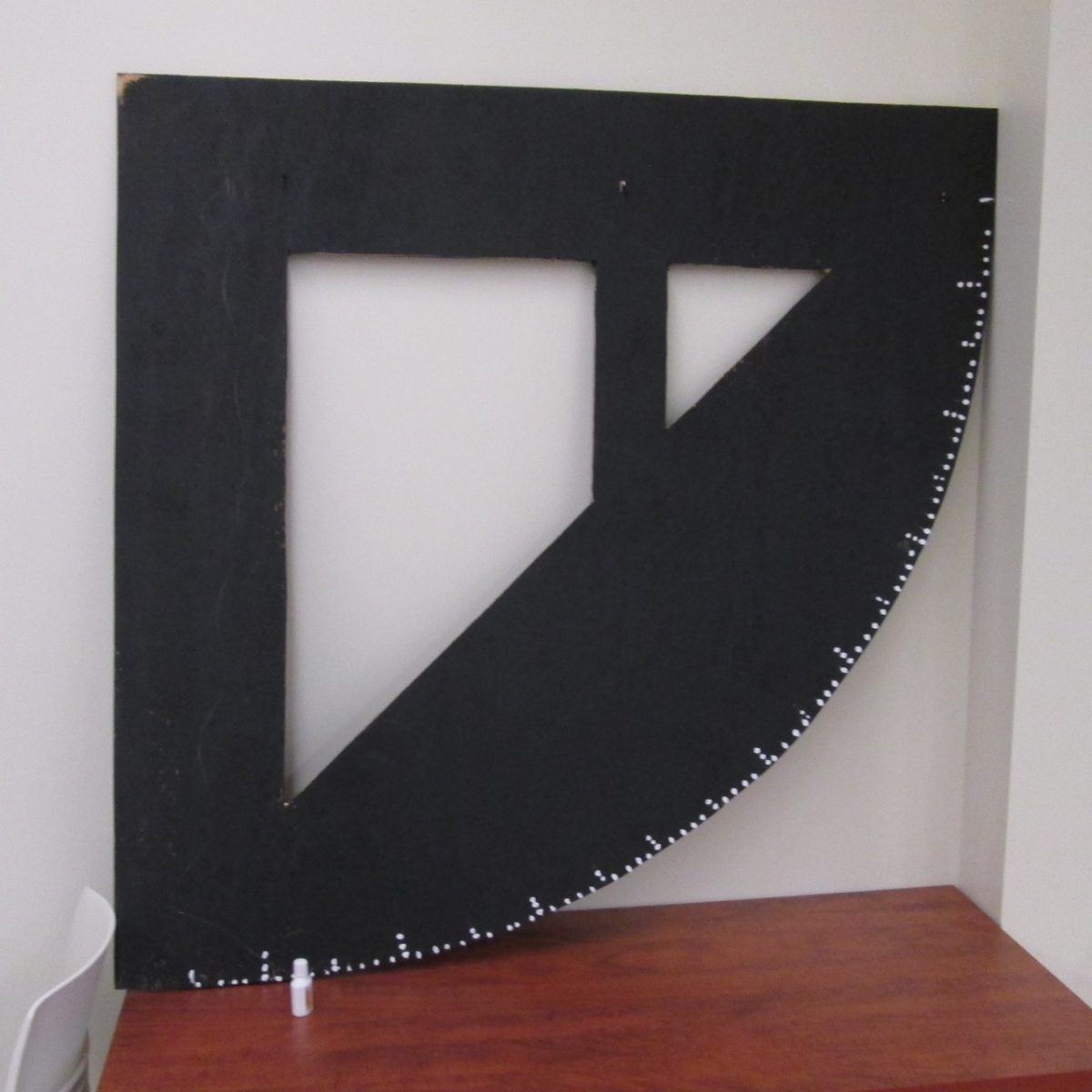
Figure 5. Completed quadrant from Fall 2014 Ancient Mathematical Astronomy class (photograph by Toke Knudsen)
The above is a photo of the finished quadrant. It is not entirely clear from the photo, but the top edge of the quadrant has three sights lined up properly. The small white bottle seen at lower left is suspended from the top-left corner of the instrument and serves as a plumb. The circular edge of the instrument has the degrees from 0 to 90 marked on it.

Figure 6. Students demonstrate the use of their quadrant in Fall 2014 Ancient Mathematical Astronomy class (photograph by Toke Knudsen)
The quadrant can be used practically, as seen in the above photo of the members of the group demonstrating how to use the instrument to the rest of the class. The small white bottle is seen hanging from the quadrant at the right side of the leftmost table, marking an angle on the instrument. The quadrant's accuracy, however, was not great since the marks for the degrees were not marked accurately enough.
Bridging the Gap Between Theory and Practice: Astronomical Instruments - Two Sextants
Two Sextants
A sextant is an instrument used to measure the angle between two objects, though especially between a heavenly body and the horizon; that is, the heavenly body's altitude. As such, a sextant serves the same purpose as a quadrant. However, the sextant has a much greater accuracy than a quadrant. In particular, a small sextant offers greater accuracy than a large quadrant.
For more information about the sextant, the Starry Messenger Project, developed by the Whipple Museum of the History of Science and the Department of History and Philosophy of Science at Cambridge University, has a website dedicated to the quadrant and the sextant at http://www.hps.cam.ac.uk/starry/quadrant.html.
Two groups undertook to design a sextant, one in Fall 2010 and one in Fall 2014.
The sextant designed in Fall 2010 was constructed from two mirrors and parts made using the 3D printer.
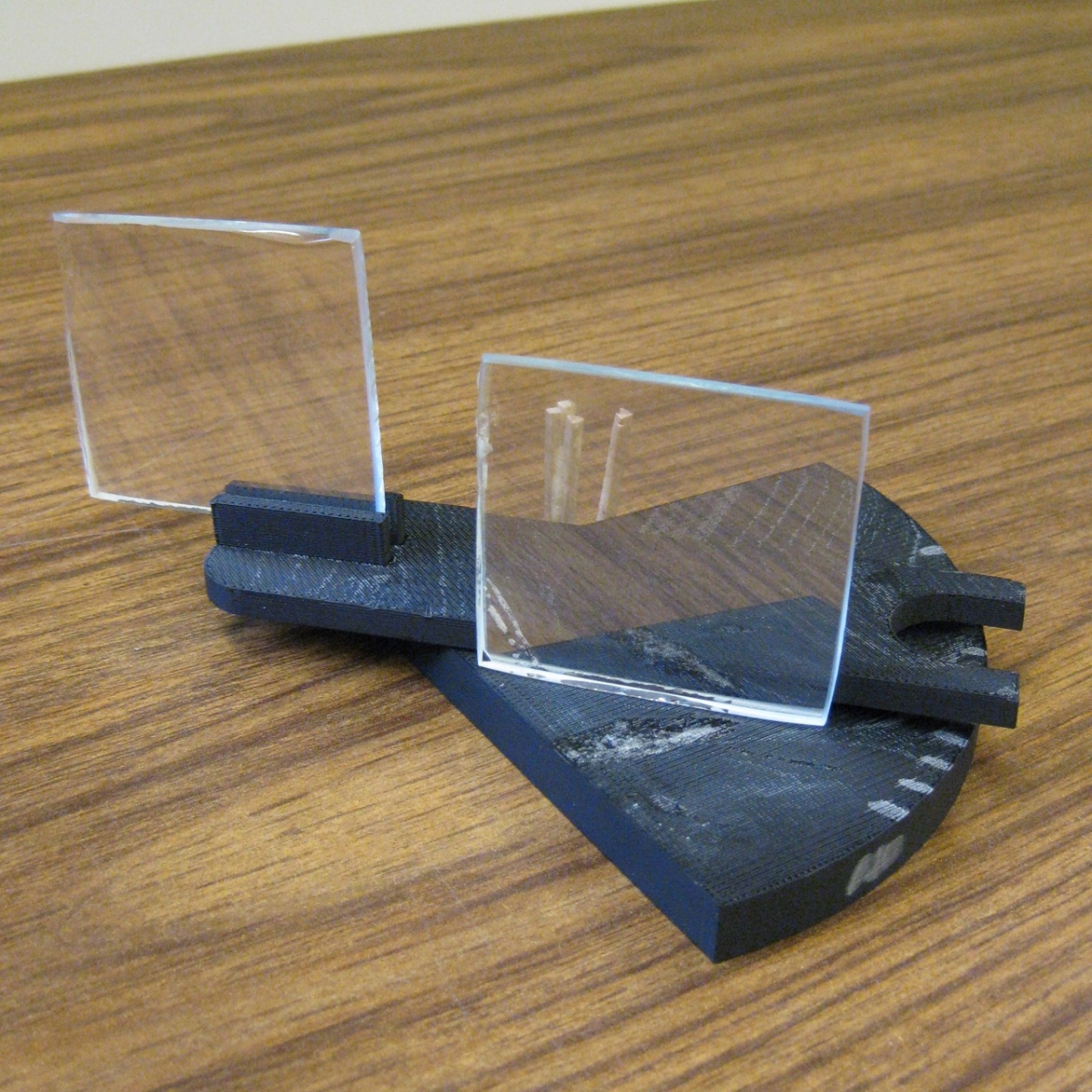
Figure 7. Student-built sextant from Fall 2010 Ancient Mathematical Astronomy class (photograph by Toke Knudsen)
The above photo shows the sextant from Fall 2010. The sextant did not work. The parts of the instrument could not move as they should, and it had no working sight.
The sextant designed in Fall 2014 was made of wood and metal parts. This sextant was designed and constructed entirely by the students, who used their own tools and material for the construction part.
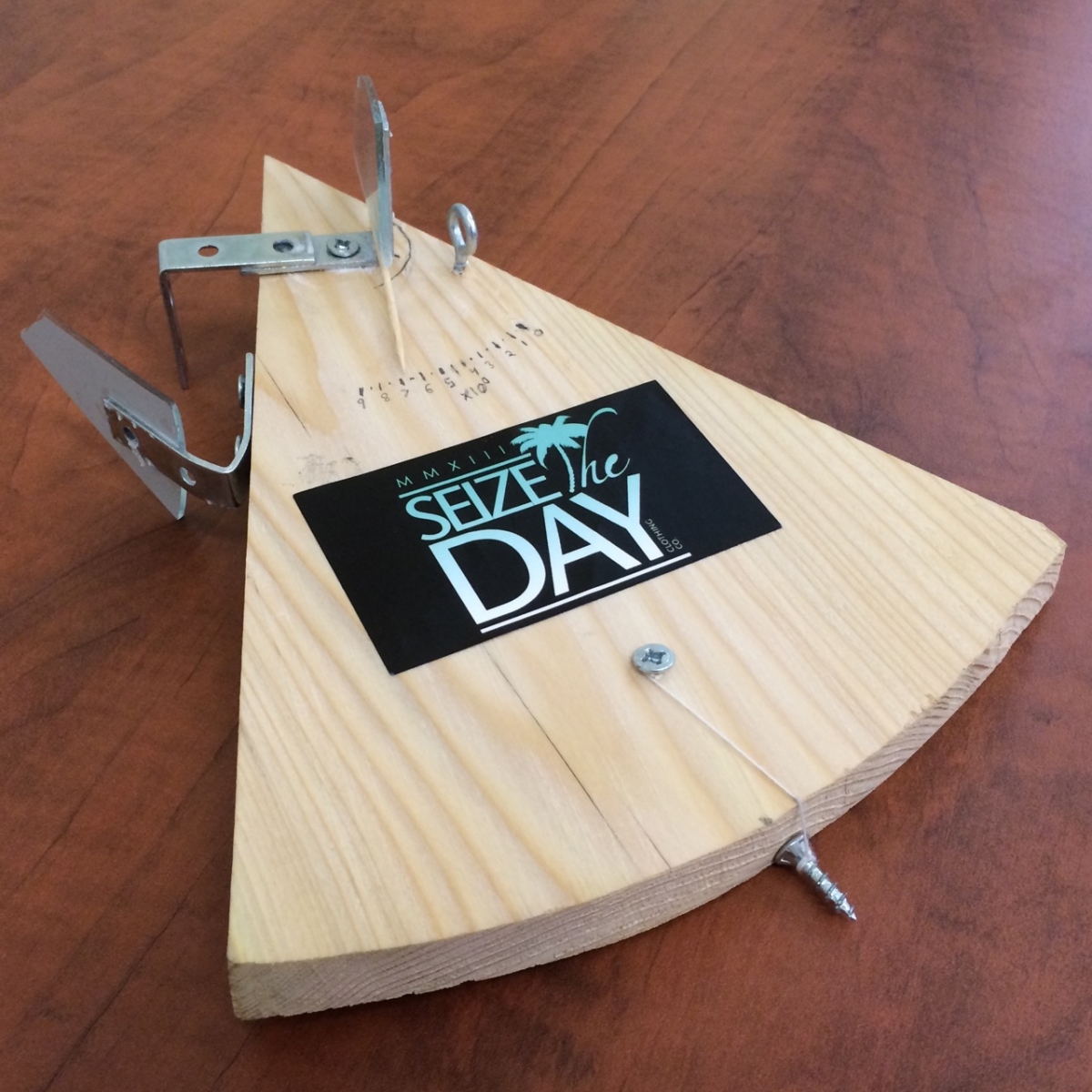
Figure 8. Student-built sextant from Fall 2014 Ancient Mathematical Astronomy class (photograph by Toke Knudsen)
The above photo shows the sextant from Fall 2014. A screw is suspended by a string from the base of the instrument. When the string covers the pencil mark on the circular edge of the base, the instrument is aligned correctly. The mirror at the top can then be adjusted, and the toothpick attached to it marks an angle. The metal loop at right functions as a sight. The sextant works as it should. The students estimated that its accuracy is around 5 degrees.
Bridging the Gap Between Theory and Practice: Astronomical Instruments - An Astrolabe, a Jacob’s Staff, and a Telescope
An Astrolabe, a Jacob’s Staff, and a Telescope
Astrolabe
An astrolabe is a complex instrument that has multiple uses, including determining and predicting the positions of the heavenly bodies.
For more information about the astrolabe, the Museum of the History of Science at Oxford University has a website dedicated to the astrolabe at http://www.mhs.ox.ac.uk/astrolabe/. In particular, there is a presentation on how to use an astrolabe to tell time at http://www.mhs.ox.ac.uk/exhibits/using-an-astrolabe-1/. In addition, Convergence has an image of a beautiful Italian astrolabe from 1558 CE at http://www.maa.org/publications/periodicals/convergence/mathematical-treasures-italian-astrolabe.
One of the groups in Fall 2010 ambitiously decided to design an astrolabe. It soon turned out that computing the lines to be drawn on the instrument was a difficult task for the students, and, in addition, that etching them on the instrument would be impossible to do with the means at our disposal. We therefore decided to photocopy the model of an astrolabe in the textbook onto transparency sheets and then attach the sheets on a base of plexiglass. This provided us with a working and nice-looking astrolabe, though a consequence was that the astrolabe was configured for the latitude of Seattle, Washington, not Oneonta, New York.
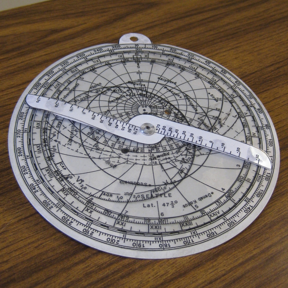
Figure 9. Student-built astrolabe from Fall 2010 Ancient Mathematical Astronomy class (photograph by Toke Knudsen)
A photo of the astrolabe constructed in the course is shown above. It worked as it should.
Based on the students' work with designing an astrolabe in Fall 2010, I decided to recommend against choosing this as an instrument in Fall 2014 when one group proposed to make a large one out of wood (the group decided to design a quadrant instead).
Jacob’s staff
A Jacob's staff, also known as a cross-staff, is an instrument used to measure the angular distance between two heavenly bodies.
For more information about the Jacob's staff, Epact, an electronic catalogue of medieval and renaissance scientific instruments from four European museums, has an article dedicated to the cross-staff at http://www.mhs.ox.ac.uk/epact/article.php?ArticleID=5.
One of the groups in Fall 2010 decided to design a Jacob's staff. While both Anderson and I felt that the instrument was probably too simple, I allowed it to go ahead to get more experience with students designing instruments. For constructing the instrument, the students made use of only materials from a local office supply store, and no use was made of the 3D printer or other resources at SUNY Oneonta.
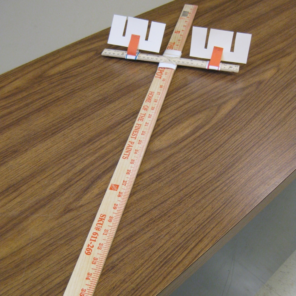
Figure 10. Student-built Jacob’s staff from Fall 2010 Ancient Mathematical Astronomy class (photograph by Toke Knudsen)
The above photo shows the Jacob's staff from the course. The instrument worked, though the paper on the smaller ruler was not stiff enough, nor attached firmly enough, to provide reasonable accuracy.
Telescope
A telescope is an instrument that uses lenses or mirrors (or both) to gather light, thereby allowing the user to directly observe distant objects.
For more information about the telescope, the Starry Messenger Project, developed by the Whipple Museum of the History of Science and the Department of History and Philosophy of Science at Cambridge University, has a website dedicated to the telescope at http://www.hps.cam.ac.uk/starry/galtele.html.
One group in Fall 2014 decided to design a telescope. Anderson and I were both positive about the idea. However, during the semester we found that we couldn't be sure that lenses bought online could be effectively fitted into the tubes we had available. As such, the group ended up purchasing and assembling a telescope kit instead.
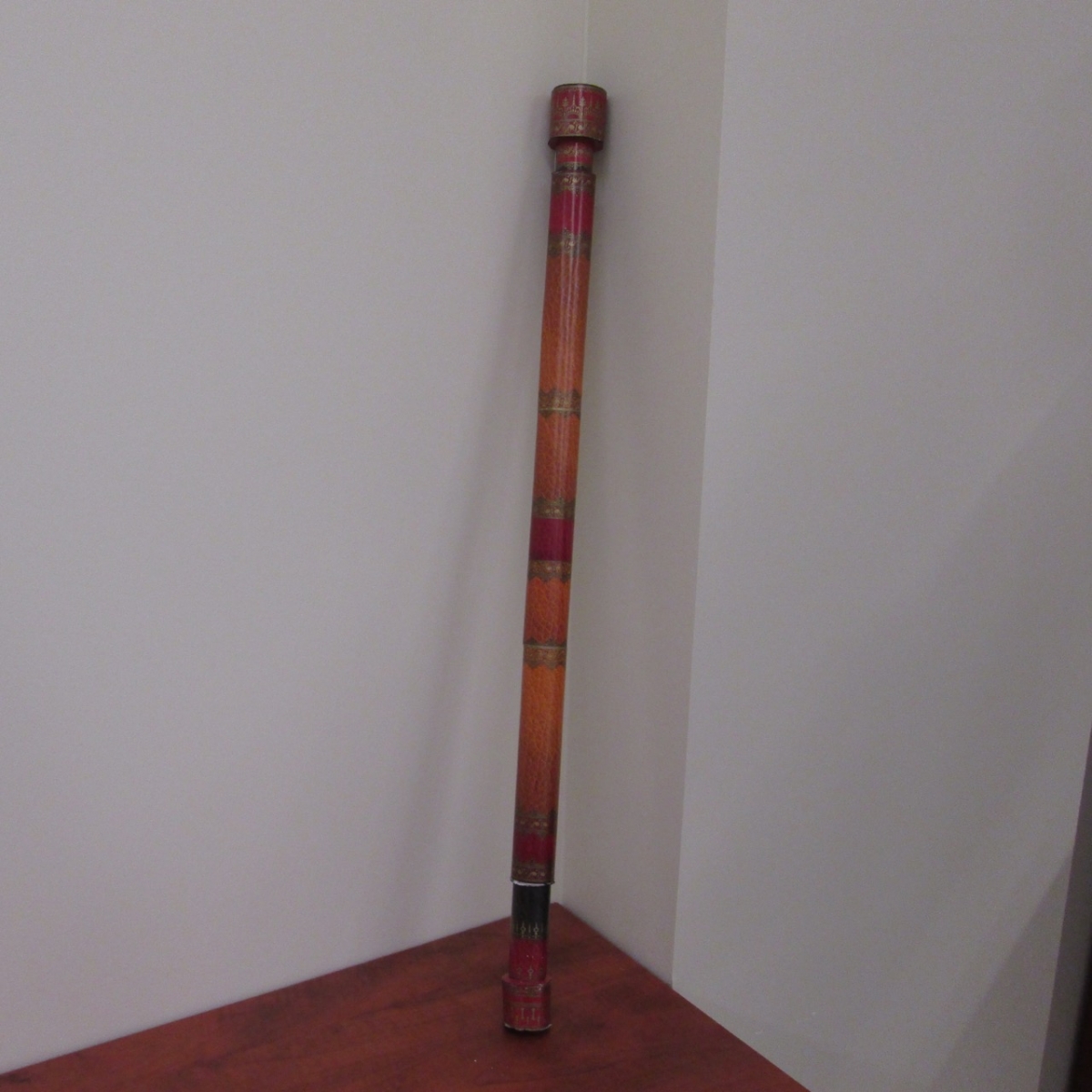
Figure 11. Student-built telescope from Fall 2014 Ancient Mathematical Astronomy class (photograph by Toke Knudsen)
The above photo shows the telescope. The telescope is a refractor (rather than a reflector), meaning it uses lenses to create a magnified image for the user. The instrument was harder to assemble for the students than expected, but it worked. However, we did not have sufficient time (or appropriate weather) to fully test it.
Bridging the Gap Between Theory and Practice: Astronomical Instruments - Three Sundials
Three Sundials
A sundial is a device by which the time of day can be determined by a shadow cast by the sun.
For more information about sundials, the Starry Messenger Project, developed by the Whipple Museum of the History of Science and the Department of History and Philosophy of Science at Cambridge University, has a website dedicated to sundials at http://www.hps.cam.ac.uk/starry/sundials.html.
Two groups decided to design sundials in Fall 2010. One chose to design only a plane sundial, whereas the other designed both a plane and an armillary sundial. All three sundials were constructed with components created by the 3D printer with the exception of the bases of the two plane sundials and the narrow metal rod which holds the armillary sundial.
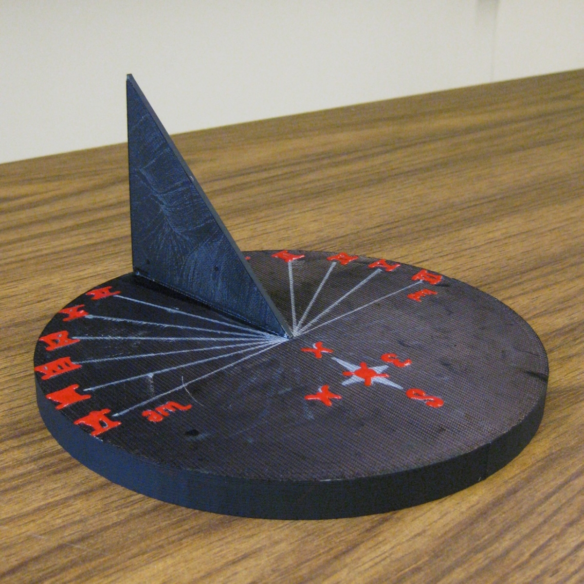
Figure 12. Student-built plane sundial from Fall 2010 Ancient Mathematical Astronomy class (photograph by Toke Knudsen)
The above photo is of the plane sundial designed by the first group. Although we did not end up having enough time (or sunshine) to really use the instrument, it worked.

Figure 13. Another student-built plane sundial from Fall 2010 Ancient Mathematical Astronomy class (photograph by Toke Knudsen)
The above photo is of the plane sundial designed by the second group. As with the previous sundial, we did not have enough time to fully use it, but it, too, worked.
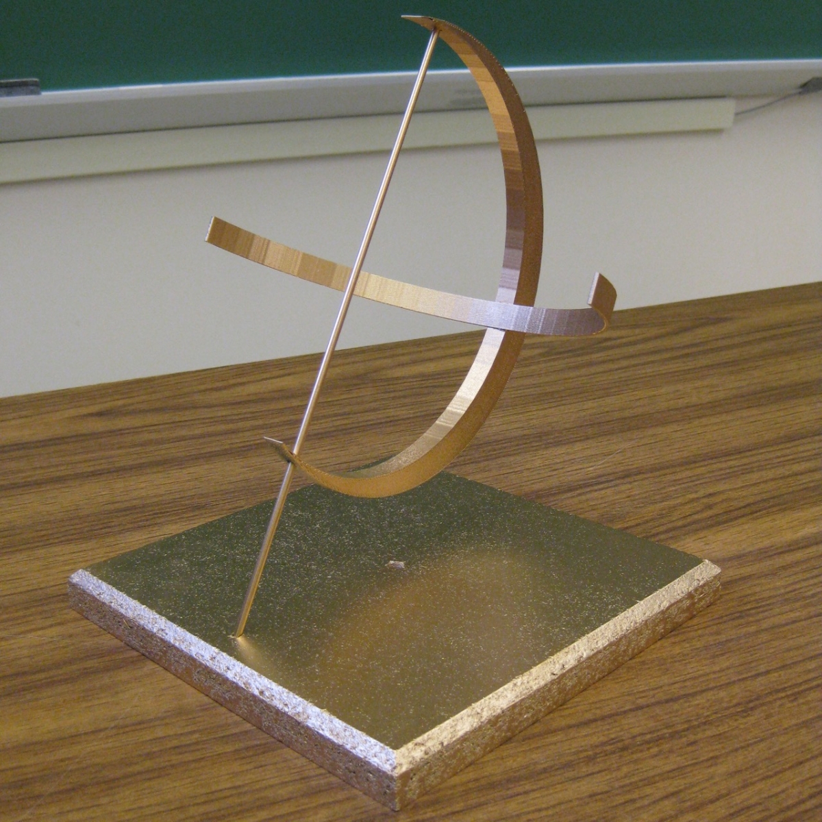
Figure 14. Student-built armillary sundial from Fall 2010 Ancient Mathematical Astronomy class (photograph by Toke Knudsen)
The above photo shows the armillary sundial designed by the second group. When in use, the metal rod throws a shadow on the instrument, which can be used to tell the time. The instrument is incomplete in that no lines corresponding to times had been made on it at the time that the photo was taken. With proper lines, the instrument would work.