- About MAA
- Membership
- MAA Publications
- Periodicals
- Blogs
- MAA Book Series
- MAA Press (an imprint of the AMS)
- MAA Notes
- MAA Reviews
- Mathematical Communication
- Information for Libraries
- Author Resources
- Advertise with MAA
- Meetings
- Competitions
- Programs
- Communities
- MAA Sections
- SIGMAA
- MAA Connect
- Students
- MAA Awards
- Awards Booklets
- Writing Awards
- Teaching Awards
- Service Awards
- Research Awards
- Lecture Awards
- Putnam Competition Individual and Team Winners
- D. E. Shaw Group AMC 8 Awards & Certificates
- Maryam Mirzakhani AMC 10 A Awards & Certificates
- Two Sigma AMC 10 B Awards & Certificates
- Jane Street AMC 12 A Awards & Certificates
- Akamai AMC 12 B Awards & Certificates
- High School Teachers
- News
You are here
Modeling the Mirascope Using Dynamic Technology - 4. Using the Simulation: Explorations and Exercises
Once we have constructed a mathematical mirascope, we can use it to ask in-depth questions about the mirascope and the way it works. In this section, we discuss how the simulation can be used for exercises and open-ended explorations.
4.1 Is the Whole Image Visible?
First of all, we want to see how an object placed at the bottom of the mirascope can be projected outside, using the “Trace On” feature of GeoGebra. With Trace turned on for both points \(P\) and \(J\), we can draw a small shape by dragging point \(P\), which is projected simultaneously to the top part of the mirascope (Figure 7a). Interestingly, the image is reflected about the \(y\)-axis in contrast to the orientation of the original object, which is consistent with a physical mirascope. It is noteworthy that in Figure 7a, the image is not entirely outside the mirascope, which means the observer can not see the whole image of the object. What might be the problem?
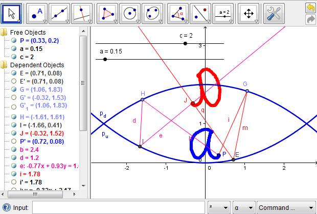
Figure 7a: A small shape is projected to the top part of the mirascope; only part of the image is actually visible.
To address the problem above, we can explore the effects of the vertical distance between the two parabolas on the position of the image. For example, what would happen if the two parabolas are farther apart? Since we used a slider for the parameter \(c\), we can now drag the point on it to change the \(c\) value to any reasonable number and simulate the mirage effect (Figure 7b). Similarly, what would happen to the image if the two parabolas are very close or, in other words, \(c\) has a small positive value? What might be an ideal case where the whole image is projected outside the mirascope? We leave these questions as exercises for the readers.
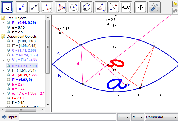
Figure 7b: When the two parabolas are far apart, a small shape is projected within the mirascope, invisible to the observer.
[Open a dynamic GeoGebra worksheet in a new window.]
4.2 Are More Light Rays Necessary to Locate the Image of a Point?
Second, we want to see if there is need for more light rays in order to uniquely locate the image of point \(P\). In the previous steps, we assumed that there is a certain light ray that leaves point \(P\) and reaches the upper parabola at a certain point, for example, point \(G\) or \(H\). We did not impose any constraint on the position of point \(G\) or \(H\). Therefore, points \(G\) and \(H\) could be anywhere on the upper parabola. To see if we need more light rays, we can turn on the Trace feature for the light ray that leaves the mirascope and allow point \(G\) or \(H\) to move along the upper parabola. As shown in Additional Figure 7c, all the resulting light rays intersect at the same point, which implies that we only need to model two light rays in order to locate the image of point \(P\), which is point \(J\) in the Figure 6f.
4.3 Exercises
We now pose a few questions to entertain the readers' curiosity, inviting them to experiment with the simulation and ask other interesting questions of their own choice. Either one of the previous web pages can be used as a starting point with a varied degree of support and complexity. To facilitate the exploration, we provide a full-sized mirascope, which can be re-exported as a web page or saved as a GeoGebra file by following options in the File Menu.
Exercise 1. The simulation allows us to answer questions about special cases. Using the mirascope provided above, please find out what would happen if the two parabolas are close to each other? (see Additional Figure 7d).
Exercise 2. In a real mirascope, the two parabolas are aligned in such a way that the vertex of one is at the focus of the other. In section 2.2, we discussed a method to find the focus of a parabola. Using that method, find the focus of the upward parabola. Then, change the value of \(c\) so that the vertex of the downward parabola is at the focus of the upward one. Simulate the mirage effect and describe what you see (dynamic web page).
Exercise 3. Distortion occurs when the object is projected by the mirascope. Change the relative distance between the two parabolas and see how it affects the amount of distortion.
Exercise 4. For an observer to see the image projected on top of the mirascope, there needs to be an opening in the top parabola. Given the size of a small object, how can we find the right size for the opening? Hint: the opening should be large enough for each point of the object to be projected outside. By tracing both of the outgoing light rays, we can determine the size of the opening (see Additional Figure 7e).
Exercise 5. As mentioned in section 2.2.1 about a parabolic mirror, when the eye, the object, and the focus are aligned in certain ways, the observer may be able to see a clear image of the object. Using methods discussed above, find what the observer may be able to see in such special cases (see Additional Figure 9 or a dynamic web page).
4.4 Managing Complexity
Finally, we reiterate the importance of complexity management during a design process. Since there are several layers of algebraic and geometric operations involved, we may get overwhelmed, at least visually, by the intermediate objects created in modeling the mirascope. Therefore, we should conduct some maintenance work at each step, both cognitively and logistically, before proceeding to the next one. GeoGebra provides a convevnient feature for hiding any object. To do so, we could right click on an object and toggle "Show Object," or, alternatively, we could toggle the radio button to the left of each object definition. Furthermore, we could define a new tool to simplify a procedure that is useful in subsequent phases of design. A full picture of the mirascope project is illustrated in Figure 8, which highlights the need to manage complexity in a complex design project.
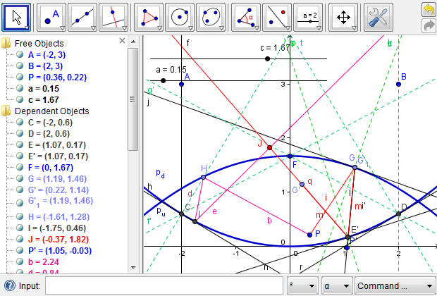
Figure 8: The full picture of the mirascope project, which shows the significance of managing complexity in the design processes.
Lingguo Bu (Southern Illinois University Carbondale), "Modeling the Mirascope Using Dynamic Technology - 4. Using the Simulation: Explorations and Exercises," Convergence (May 2011), DOI:10.4169/loci003595